Seismometers
Seismic Monitoring System
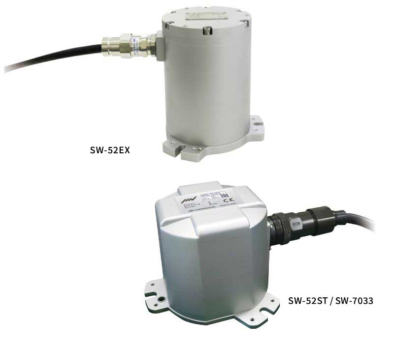
(SW-52EX / SW-52ST / SW-7033)
Uses high resolution servo accelerometer which can detect microearthquakes
This is an seismic monitoring system that employs a high-precision servo-type acceleration sensor to
obtain an alarm output for control during an earthquake.
SW-52EX can be used in gas/dust explosion-proof areas such as petrochemical/hydrogen plants and
manufacturing plants to minimize secondary disasters caused by earthquakes.
Features
Reliable accuracy
-
Built – in servo type accelerometer is also used for detection of micro-tremor. Both indication setting and alarm setting is 1 gal step.
-

Dust-proof and waterproof structure
-
It is ideal to install the seismometer on the common foundation to catch the motion of earthquake correctly. IMV seismic monitoring systems adopt IP67 waterproof structure which is able to be installed outside or dusty environments.
-

Available to large-scale earthquake monitoring
-
The peak of motion in any direction can be surely captured by vector composition of the accelerations detected by the accelerometers arranged in three directions. The measurable acceleration range up to 5000 gal prepare against the large-scale earthquake.
-

Flame-proof structure * Only SW-52EX
The container is constructed to withstand the pressure when explosive gas explosion occurs and not to catch fire.
Standard communication method
RS-485(ModBus)is adopted.
System Composition

SW-52ST uses a servo acceleration sensor, and SW-7033 uses a MEMS acceleration sensor.
By adopting a MEMS acceleration sensor, the SW-7033 is cheaper than the SW-52ST.
Flame-proof / dust-ignition-proof specification (SW-52EX)
| Certification | Ex db IIB+H2 T6 Gb (IECEx, ATEX) Ex d IIB+H2 T6 Gb (TIIS) Ex tb IIIC T120℃ Db (IECEx, ATEX,TIIS) |
|
|---|---|---|
| Certification No. | IECEx DEK 16.0004X DEKRA 16ATEX0005 X TIIS TC22341X |
|
| Compliance standard | IECEx | IEC 60079-0:2011 IEC 60079-1:2014-06 IEC 60079-31:2013 |
| ATEX | EN 60079-0:2012+A11 EN 60079-1:2014 EN 60079-31:2014 |
|
| TIIS | Explosion-protected electrical installations in general industries JNIOSH-TR-46-1:2015 JNIOSH-TR-46-2:2015 JNIOSH-TR-46-9:2015 |
|
Classification of explosive gas
Explosion-proof performance display
Group:ⅡA,ⅡB,ⅡCC
Temperature class:T1,T2,T3,T4,T5,T6
| 450℃ ≧ T1 > 300℃ | 300℃ ≧ T2 > 200℃ | 200℃ ≧ T3 > 135℃ | 135℃ ≧ T4 > 100℃ | 100℃ ≧ T5 > 85℃ | 85℃ ≧ T6 | |
|---|---|---|---|---|---|---|
| ⅡA | NH3, CO, C2H6, C7H8, C3H8, CH4 |
C2H6O, C4H10O, C4H10, C5H8O2, |
C6H14, gasoline, Kerosene, C5H12 |
C2H4O, C3H9N |
Ethyl nitrite | |
| ⅡB | HCN, C3H3N, Coal gas |
C4H4O, Ethyl acrylate, C2H4 |
C2H6O, C6H12, C5H8 |
|||
| ⅡC | H2 | C2H2 | CS2 | C2H5NO3 |
Main explosive gas targeted by this product
Classification of explosive dust (GroupⅢ)
| Type of dust | Electric resistance | Representative materials | |
|---|---|---|---|
| ⅢA |
Combustible flyers |
– |
Textiles such as rayon, cotton, sisal hemp, jute |
| ⅢB | Non-conductive dust Size ≦ 500 μm |
Electric resistance > 103Ωm | Powder such as cereal flour, sugar, toner, synthetic resin powder |
| ⅢC | Conductive dust Size ≦ 500 μm |
Electric resistance ≦ 103Ωm | Metal powders such as carbon black, aluminum, magnesium |
Outline
Drawings
*Include Imperial measurements
SW-52EX

SW-52ST / SW-7033

