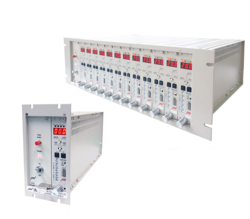
Vibration monitoring System
Contact Sensor Vibration Monitoring System
(VM-9301 series)
Permanent vibration monitoring for systems such as motor, pump and blower.
Monitoring system suitable for multi-channel measurement. Frequency range, measurement range or output signal can be customized.
Features
Compatible with conventional systems

A wide range of compatible sensors
Selectable from electrodynamic velocity sensor or piezoelectric sensor.
Electrodynamic velocity sensors
Specialized in medium frequency (up to 1,000 Hz) vibration detection. Suitable to velocity monitoring.
| Model | VP-3144C/D | VP-3354
A (Horizontal only) |
VP-3364
A (Vertical only) |
VP-3134AEX | VP-3213 AC/AD | VP-3133 HEX/VEX |
|---|---|---|---|---|---|---|
| Sensitivity | 10 mV/(mm/s) | 10 mV/(mm/s) | 10 mV/(mm/s) | 17.5 mV/(mm/s) | 17.5 mV/(mm/s) | |
| Natural frequency | 14 Hz | 14 Hz | 14 Hz | 4.5 Hz | 4.5 Hz | |
| Operating temperature range | -20 to +80℃ | -20 to +80℃ | -20 to +70℃ | -20 to +70℃ | -20 to +70℃ | |
| Structure | Drip-proof (Equivalent to IP32) | Water-proof (Equivalent to IP66) | Flame-proof (EX d ⅡBT4Gb) | Drip-proof (Equivalent to IP32) | Flame-proof (EX d ⅡBT4Gb) | |
| Outward appearance |
 Type C |

|

|

|
 Type AC |

|
| Notes | High sensitivity / medium frequency |
Medium frequency / 2-directional |
Medium frequency / 3-directional |
Medium frequency | Low frequency / horizontal only |
Low frequency / HEX (horizontal only), VEX (vertical only) |
Other sensors for high temperature or waterproof are also available. Please contact .
Piezoelectric sensors
Specialized in high frequency (over 1,000 Hz) vibration detection. Suitable to acceleration monitoring.


Multi-channel
Maximum 12 channel per 1 system is available. Range and function can be set individually per every channel.
Application Example
Cables are laid out between sensors located on a large sized motor of home power generator and a monitoring system housed in a control panel. Monitoring systems can monitor vibration values and output the alarm in an emergency.

Outline
Drawings
*Include Imperial measurements

Unit: mm
| A | B | C | D | E | F | G | H | I | ||
|---|---|---|---|---|---|---|---|---|---|---|
| Channel | Type 1 channel | 90 | 170 | 300 | 88 | 132 | 90 | 148 | 162 | 50 |
| Type 3 channel | 210 | 149 | 300 | 160 | 132 | 180 | 143 | 100 | 195 | |
| Type 6 channel | 300 | 149 | 300 | 250 | 132 | 270 | 143 | 100 | 285 | |
| Type 9 channel | 390 | 149 | 300 | 340 | 132 | 360 | 143 | 100 | 375 | |
| Type 12 channel | 480 | 149 | 300 | 430 | 132 | 450 | 143 | 100 | 465 | |
